A frequency inverter (often also called a VFD, inverter, or drive) is far more than just a component for speed control. It acts as an intelligent link between the rigid power supply and the flexible power demand of a modern machine. While an electric motor connected directly to the conventional 50 Hz mains can only run at one fixed speed, the frequency inverter enables stepless and low-loss adjustment of speed and torque.
This technology is the key to automation: it allows mechanical processes to be controlled precisely, reduces stress on components, and—especially important in times of rising electricity prices — significantly lowers energy consumption.
What is a frequency inverter?
A frequency inverter is an electronic device that makes the speed of an electric motor variably controllable. Without an inverter, a three-phase motor connected directly to the public power grid would run rigidly at the mains frequency (50 Hz in Europe) – meaning it would have only one fixed speed.
The frequency inverter removes this rigid link. It allows speed and torque to be adjusted steplessly to the actual needs of the machine. Whether a conveyor belt has to start slowly, a fan is only required to run at half power, or a centrifuge must accelerate precisely: the frequency inverter acts as the “intelligent brain” between the power supply and the motor. In industrial environments, these devices are now used almost everywhere – from small drives with just a few watts of power to large drives in the megawatt range. They mainly control:
- Three-phase asynchronous motors (the robust industrial standard)
- Synchronous motors (for highly dynamic applications)
- Synchronous reluctance motors (for maximum energy efficiency)
How does a frequency inverter work?
To understand how a frequency inverter turns a fixed mains voltage into a variable output voltage, it is worth taking a look inside the housing. The process of power conversion takes place in three logical stages, which decouple the motor from the public power grid:
Which control methods are used?
Not every application has the same requirements for precision. Modern inverters from Mitsubishi Electric therefore support different control methods:
- U/f Control: This is the simplest method. Here, voltage (U) and frequency (f) are increased or decreased in a fixed ratio. It is robust and perfectly sufficient for applications such as pumps or fans, where maximum dynamic performance is not required.
- Vector Control (Sensorless Vector Control): Vector control is significantly more advanced. Here, the processor in the inverter calculates a mathematical model of the motor in real time. It can control the flux-producing current and the torque-producing current separately. The advantage: the motor can maintain high torque even at very low speeds and dynamically compensate for load changes without the speed dropping — often without any external encoder.
Why is the use of frequency inverters economically sensible?
The use of this technology pays off twice in practice: by protecting the machine and by reducing operating costs.
How does the inverter protect the mechanics?
A motor that is started directly from the mains (“direct-on-line start”) draws six to eight times its rated current at the first moment and accelerates abruptly to full speed. This mechanical shock puts enormous stress on gearboxes, couplings, belts, and bearings. A frequency inverter, on the other hand, starts the motor smoothly via an adjustable ramp. This eliminates current peaks and drastically reduces mechanical wear, which extends maintenance intervals and minimizes downtime.
How much energy can you actually save?
Especially in flow machines such as pumps and fans, the savings potential is enormous. These applications follow physical laws (affinity laws) in which power consumption increases with the third power of speed. This means in reverse: reducing the speed by just 20% already lowers energy demand by about 50%. Instead of mechanically restricting an air or water flow with throttling valves (which wastes energy), the frequency inverter adjusts the motor’s power exactly to actual demand.
Expert Tip: The inverter is only one part of the equation. The biggest efficiency gains are achieved in the system as a whole. In particular, the combination of a modern frequency inverter and a magnet-free synchronous reluctance motor enables IE5-class efficiency levels that go far beyond legal standards.
Learn more here about the interaction between frequency inverters and synchronous reluctance motors!
What does “Functional Safety” mean?
In the past, motors had to be hard-disconnected from the mains in an emergency using external contactors. Today, safety technology is integrated directly into the frequency inverter. Functions such as STO (Safe Torque Off) ensure that the control of the power semiconductors is safely interrupted. The motor can no longer generate torque and coasts to a stop. Advanced functions like SS1 (Safe Stop 1) first decelerate the motor in a controlled manner before shutdown. This greatly simplifies wiring in the control cabinet and enables smarter safety concepts, allowing the system to restart more quickly after a fault.
Which frequency inverter is right for my requirements?
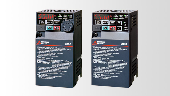
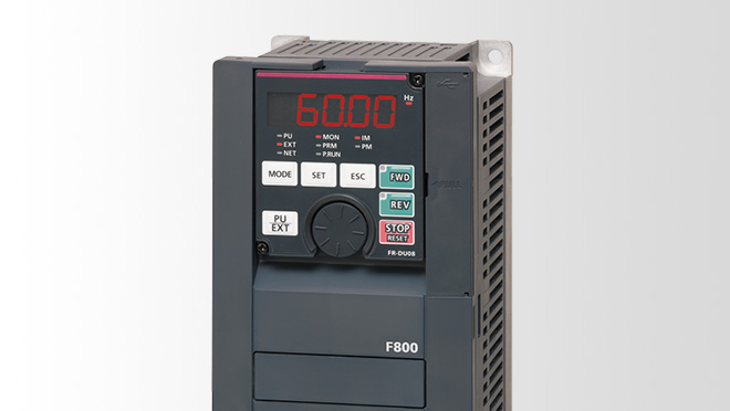
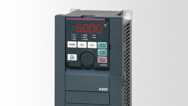
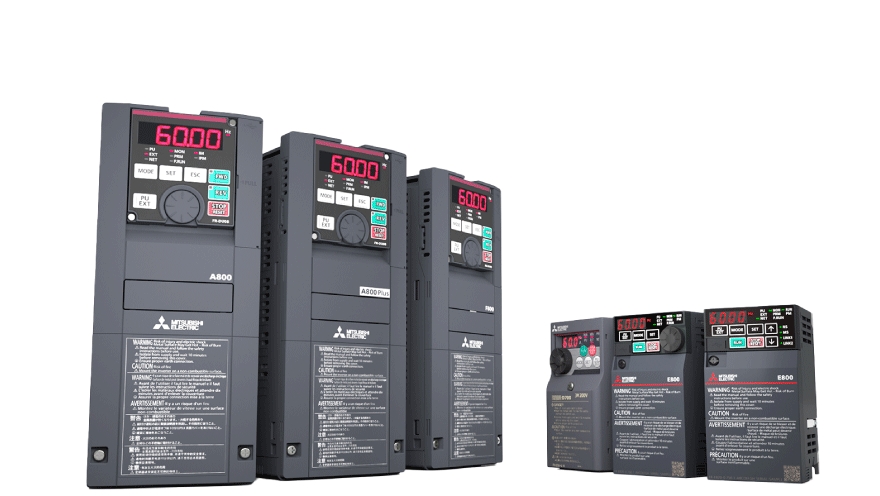
Based on the technologies mentioned above, Mitsubishi Electric offers a tiered product portfolio. Choosing the right device depends on the task that needs to be accomplished.
All our frequency inverters at a glance
Frequently asked questions about frequency inverters (FAQ)
Can existing systems be retrofitted?
Yes, this is common practice. Frequency inverters can be integrated into existing control cabinets to control older motors more efficiently. However, it must be checked whether the insulation of the old motor is suitable for inverter operation and whether its self-cooling is sufficient at low speeds.
What Is Meant by Mains Feedback (Grid Disturbance)?
Because inverters “chop” the current (non-linear load), harmonics can be generated that put a strain on the power grid. High-quality devices have integrated chokes or filters to minimize these effects and comply with EMC guidelines.
When Does the Investment Pay for Itself?
In pump and fan applications that run continuously, the payback period (ROI) through energy savings is often less than one year. In process applications, improvements in quality and machine protection are often the main factors in the economic evaluation.
More documents for download
We’ll be happy to advise you personally!